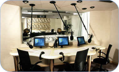
CASE STUDY:
MICROPHONE POLES FOR STUDIOS
Customer’s needs
Microphones in professional recording studio can cost up to £10,000. They are normally mounted on floor stands with a counterbalanced or clamped boom to position the microphone near the artist or instrument.
Even with relatively heavy stands it is not uncommon for them to be knocked over resulting in damage or destruction of sensitive microphones.
The client’s requirements were for a microphone boom that could be hung from the ceiling and locked in place.
how Acoustics & Studio Design works click here
It was also necessary to provide a facility to easily remove the boom from the ceiling and move it to another location in the studio without having to disconnect plugs or leave wires hanging from the ceiling or trailing along the floor.
This meant that the electrical cables and contacts had to be incorporated within the unit. The small electrical currents generated by microphones requires that the contacts of the highest quality.
The main features that the unit had to include were as follows:
• The unit had to enable the microphone to be positioned at different heights from the floor
• It had to be adjustable without any special tools or equipment by the artist or technician
• It should be possible to cover the whole floor area of a studio with a minimum number of locations
How the customer’s needs were met
A study was made of the products on the market to establish if an existing product could be modified to meet the customer’s needs. This was found to be not possible at a reasonable cost.. A design exercise was carried out to establish a detailed specification for the product.
This included:
• Establishing the typical heights at which performers would require the microphone to be.
• The area in a studio which needed to be covered
• The weight and size range of the microphones that would be supported on the boom.
• Details such as space above the ceiling, cable requirements, power and signal interference also had to be quantified.
Having evaluated a number of possible ways to satisfy the client’s requirements the most suitable design was chosen, design drawings completed and a prototype produced for client approval and testing.
The unit consists of two parts. A ceiling fitting, a number of which are fitted at various positions in the ceiling – and a telescopic microphone boom which can be fitted into any of the ceiling fittings as required.
The ceiling fittings contain a jack socket which is wired to patch panels or switching systems in the studio. The ceiling fittings consist of a ball unit which can be locked in position by twisting the microphone pole.
how Electronic Design & Programming works click here
The microphone pole is available in two or three standard lengths depending on the studio height. They are telescopic so that they can extend and be locked at the right length.
The microphone is fitted to the lower end using a standard fitting and plugged into the cable which runs up the centre of the microphone pole. The other end of the pole has a jack plug retained in a locking mechanism.
This means that when the pole is inserted into the ceiling fitting it automatically makes the electrical connection and also locks itself in the ceiling fitting.
The assembly can be moved about to position the microphone as required until a ring on the lower end of the microphone pole is twisted. This locks the ceiling fitting in whatever position it is in.
Changing the position of the microphone is just a matter of unlocking the ring moving the pole to a new position and twisting the ring to lock it in the new position.
When the studio set up needs to be changed the pole is unlocked by twisting the ring and then by twisting the ring another two turns unlocks the pole from the ceiling fitting and allows it to be removed.
Find out more info.

